
 English
 Español
 русский
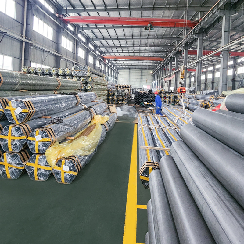
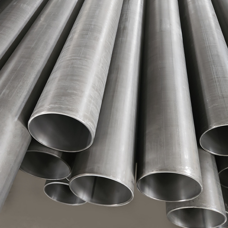
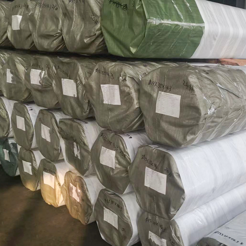
ASTM A513 Type 2 Cold-Rolled Tube – Grade 1010, 1” x 0.065” DOM Finish for Automotive Components
Cold-Rolled Steel Tube – ASTM A513 Type 2 Grades 1010, 1015, 1020, 1026 (1” x 0....

Content
A single stress fracture in a driveshaft tube can cause catastrophic failure on the highway. The steel tube inside a shock absorber, suspension arm, or chassis rail is not just a hollow piece of metal — it’s a structural element where a wrong grade choice can shorten component life by 50% or more. Material selection errors contribute to nearly 15% of chassis-related fatigue failures, according to failure analysis data seen in tier‑1 quality reviews. When you’re specifying a tube for automotive components, you’re balancing tensile strength, weldability, corrosion resistance, and cost in an environment where tolerances are measured in microns and service life is measured in hundreds of thousands of miles.
That balance becomes even tighter in modern vehicle platforms. Electrification adds battery mass, which increases torsional loads on suspension and chassis tubes. Lightweighting targets demand thinner walls with the same — or higher — fatigue resistance. Traditional rule‑of‑thumb selections no longer work. A general‑purpose ERW tube that performed adequately in a steel‑bodied saloon may fail prematurely in an EV crossover because the loading spectrum has shifted. Understanding the interaction between manufacturing process, material grade, and surface finish separates a reliable, long‑life tube from a field‑failure statistic.
This article moves past generic catalog descriptions. We’ll compare seamless, DOM, ERW, and precision cold‑drawn tubes side by side, then connect each type to real automotive sub‑systems: driveline, suspension, braking, and interior structures. You’ll also find quantitative data on surface roughness effects, a material‑grade selection table, and a repeatable decision framework that accounts for certification requirements and batch‑size economics.
Four tube manufacturing families dominate automotive applications. The differences lie in how the tube wall is formed and what post‑processing steps are applied — and those differences directly control mechanical uniformity, weld integrity, and dimensional accuracy.
| Tube Type | Key Process | Typical OD Tolerance | Weld Seam | Relative Cost | Common Automotive Use |
|---|---|---|---|---|---|
| Seamless (Hot‑Finished or Cold‑Drawn) | Pierced billet, no weld | ±0.5% — ±1% OD | None | Highest | Hydraulic cylinders, high‑pressure fuel rails, roll‑cage members |
| DOM (Drawn Over Mandrel) | ERW shell cold‑drawn over a mandrel | ±0.1 mm typical | Nearly invisible, grain‑refined | Medium‑High | Driveshafts, steering columns, shock absorber bodies |
| ERW (Electric Resistance Welded) | Strip formed and welded, as‑welded or annealed | ±0.2 — 0.5 mm | Visible, remains in heat‑affected zone | Lowest | Seat frames, cross‑car beams, exhaust hangers |
| Precision Cold‑Drawn (CDW/CDS) | Welded or seamless shell cold‑drawn to tight dimensions | H8–H9 (ID), ±0.05 mm possible | Minimized after drawing | Medium | Shock absorber rods, bushing sleeves, transmission components |
For driveline components, DOM tubes bridge the gap between cost and performance. A cold-drawn welded tube for driveshaft applications typically holds a wall thickness tolerance of ±0.1 mm, which directly influences residual imbalance — every 0.1 mm of eccentricity can increase dynamic unbalance by 15–20 g·cm in a 1.5‑metre shaft. That’s why OEMs specify DOM over plain ERW for propshafts, even when the raw material cost is 20–30% higher.
Seamless tubes dominate in hydraulic and safety‑critical circuits. The absence of a weld line removes the weakest link in high‑cycle pressure fatigue. However, seamless does not automatically mean better — many modern DOM grades achieve comparable burst strength when the welded zone is properly heat‑treated and drawn. Precision cold‑drawn tubes, often supplied with an ultra‑smooth ID (Ra 0.4 µm or better), are the default choice for monotube shock absorbers and hydraulic cartridge cylinders where seal longevity matters more than raw hoop strength.
Steel chemistry sets the baseline, but the actual mechanicals also depend on heat treatment. The same E355 grade can show a yield strength swing of 150 MPa depending on whether it’s supplied as‑rolled, normalized, or cold‑worked. The table below lists the most common automotive tube grades with representative properties in the delivery condition most suppliers offer for machined or formed components.
| Grade | Standard Reference | Yield Strength (MPa) min. | Tensile Strength (MPa) min. | Hardness (HRB / HB) | Typical Automotive Use |
|---|---|---|---|---|---|
| 1020 / 1026 | ASTM A513 Type 5 (DOM) | 350 – 480 | 450 – 580 | 70 – 85 HRB | Driveshaft tubes, steering shaft jackets, bushings |
| 4130 (Cr‑Mo) | ASTM A519 | 520 – 690 | 670 – 850 | 90 – 100 HRB | Motorsport roll cages, suspension links, high‑load chassis members |
| E355 | EN 10305‑1 / EN 10305‑2 | 355 (N) / 520 (C) | 490 – 650 | 150 – 200 HB | Hydraulic cylinder barrels, piston rods, structural tubes |
| 27SiMn | GB/T 17396 (China) / comparable to 27MnSi | 835 (QT) | 980 | 28 – 35 HRC | Heavy‑duty hydraulic cylinders, telescopic fork tubes |
| ST52 / S355 | DIN 2391 / EN 10305 | 355 – 520 | 490 – 630 | 150 – 190 HB | Chassis subframes, axle tubes |
1026 DOM tubes deliver the best fatigue‑life‑to‑cost ratio for rotating driveshafts, while 4130 is reserved for weight‑sensitive performance platforms where post‑weld heat treatment is already part of the manufacturing plan. E355 and ST52 dominate European suspension designs because they weld predictably and can be drawn to tight tolerance without excessive springback. The high‑strength 27SiMn grade appears mainly in heavy mobile machinery and commercial vehicles, where the quenched‑and‑tempered condition provides a yield strength over 800 MPa — but it requires careful welding procedure control to avoid heat‑affected zone softening.
Surface treatment is not a cosmetic choice. On a shock absorber tube, the difference between a zinc phosphate coating and a cataphoretic e‑coat can be 480 hours of salt spray resistance versus over 1,000 hours. Inside the tube, surface roughness directly governs seal wear: reducing the inner surface roughness (Ra) from 1.6 µm to 0.4 µm has been shown in endurance testing to extend hydraulic seal life by a factor of two or more.
| Treatment | Salt Spray (ASTM B117) hrs to red rust | Adhesion (Cross‑Cut) ISO 2409 | Typical Application | Process Notes |
|---|---|---|---|---|
| Zinc Phosphate + Oil | 72 – 150 | Not applicable | Internal storage protection, machined surfaces | Good machinability; minimal dimensional change |
| Zinc Phosphate + Cataphoretic E‑Coat | 800 – 1,200 | Grade 0 – 1 | Exposed suspension tubes, underbody structures | Uniform film thickness (15–25 µm); requires curing oven |
| Hard Chrome Plating (OD) | 500+ (base material dependent) | Not applicable | Piston rods, shock absorber outer tubes | Post‑grinding to Ra 0.2–0.4 µm; hydrogen embrittlement risk controlled by baking |
| Nitrocarburizing (Melonite / Tenifer) | 400 – 600 (plus oil seal) | Excellent compound layer adhesion | High‑cycle shock absorber rods, steering shaft tubes | Minimal dimensional growth; core hardness maintained |
For monotube shock absorber applications, the best practice is to use a shock absorber cylinder tube with controlled inner roughness — typically Ra 0.4 µm max — combined with a cataphoretic e‑coat on the outer surface. The e‑coat provides stone‑chip resistance far superior to powder coating, while the smooth ID keeps the piston seal friction low and consistent over the product’s life. In areas where aesthetic appearance matters, such as exposed coilover bodies, hard chrome plating remains the benchmark, but it adds roughly 25–35% to the tube cost compared with a high‑quality e‑coat.
A structured decision flow removes guesswork. The following five‑step sequence has been refined from dozens of production part approvals and supplier qualification programs.
This sequence prevents the most common mistake: starting the conversation with a material grade before the component’s stress state is understood. Always begin with function and loads, then let the data push you toward the right tube type.
The total cost of a tube in a production automotive component is rarely its per‑metre price. Cutting, end finishing, and the cost of rejecting a batch because the supply condition was wrong often outweigh the raw material cost. The table below compares standard stock tubes with custom‑drawn tubes that match a specific OD/ID/wall combination and surface spec.
| Factor | Standard Stock Tube | Custom‑Drawn Tube |
|---|---|---|
| Tooling Cost | None (off‑the‑shelf) | Die set amortized over order (typically $1,500–$3,000 one‑time) |
| Material Yield (cut‑to‑length) | 85–92% | 95–98% (produced to exact length) |
| Lead Time (prototype lot, <500 pcs) | 1–2 weeks (if stocked) | 3–5 weeks |
| Lead Time (production, >5,000 pcs) | 4–6 weeks | 8–10 weeks (mill schedule dependent) |
| Minimum Order Quantity | Often single lengths (3–6 m) | Typically 500–1,000 kg per dimension |
| ID Surface Finish Control | As‑drawn or as‑welded | Controlled to Ra 0.4 µm or better if required |
For low‑volume prototyping, flexibility matters more than unit price. Several specialist mills accept orders as low as 200–300 kg for precision cold‑drawn tubes, giving tier‑2 suppliers a viable path to validate a design before committing to high‑volume tooling. In these cases, the lead‑time penalty is marginal — maybe one additional week — while the engineering benefit of testing with production‑intent surface finish and tolerance is enormous.
Without the right certifications, no OEM procurement portal will let a tube supplier through the door. The baseline for production parts is IATF 16949, which adds automotive‑specific requirements on top of ISO 9001. A supplier who only holds ISO 9001 may still be acceptable for aftermarket or service parts, but not for direct OEM tier‑1 delivery.
Losing a certification — or failing to maintain a compliant process — isn't a paperwork inconvenience. It halts shipments and can lead to a containment action that freezes the entire supply chain for that part number. Selecting a tube supplier with a live IATF 16949 certificate and a track record of on‑time PPAP submissions is a risk‑mitigation decision, not a procurement formality.
Every automotive tube decision sits at the intersection of material science, process capability, and supply‑chain math. The right choice is never a single grade or process — it’s a combination that delivers the required fatigue life, dimensional consistency, and corrosion resistance within a viable total‑cost envelope. Seamless tubes offer maximum integrity for safety‑critical circuits. DOM tubes provide the best balance for rotating and structural parts. ERW remains the workhorse for formed, non‑stressed applications.
The most successful engineering teams don’t just request a quote for “tube for automotive components.” They come to the table with a clear load case, a target surface finish, and an understanding of the certification path their program requires. If you’re evaluating a new design or re‑sourcing an existing part, start with the five‑step selection framework above. Then reach out for a technical data package that includes full mill test certificates, sample spools for weld qualification, and PPAP‑ready capability data — the kind of substance that separates a reliable supply chain from a supplier questionnaire.
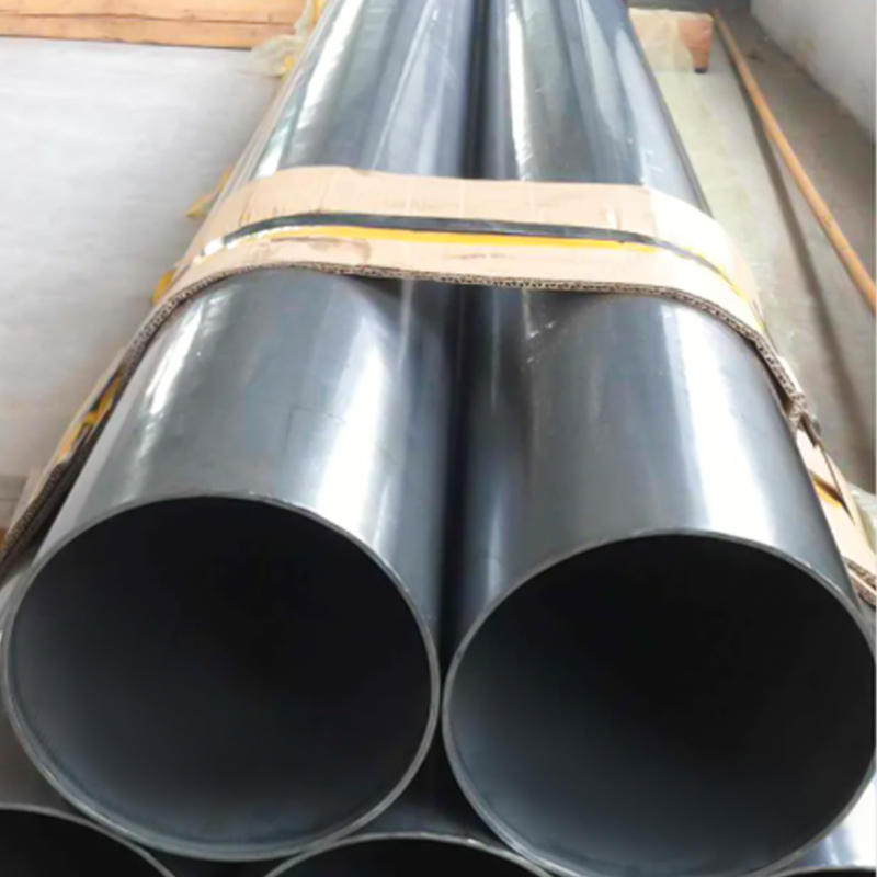
Cold-Rolled Steel Tube – ASTM A513 Type 2 Grades 1010, 1015, 1020, 1026 (1” x 0....
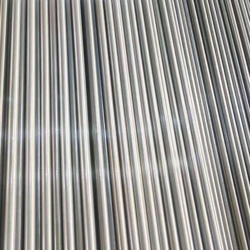
Our Welded Hydraulic Tubes are produced from cold-drawn or ERW-welded strip stee...

Our Stainless Steel Pneumatic Cylinder Tubes are precision-manufactured from 304...
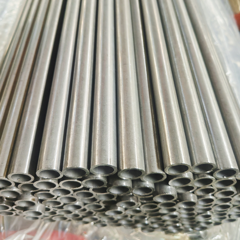
Our ASTM A519 1020 cold-drawn seamless hydraulic tubes are engineered for high-p...
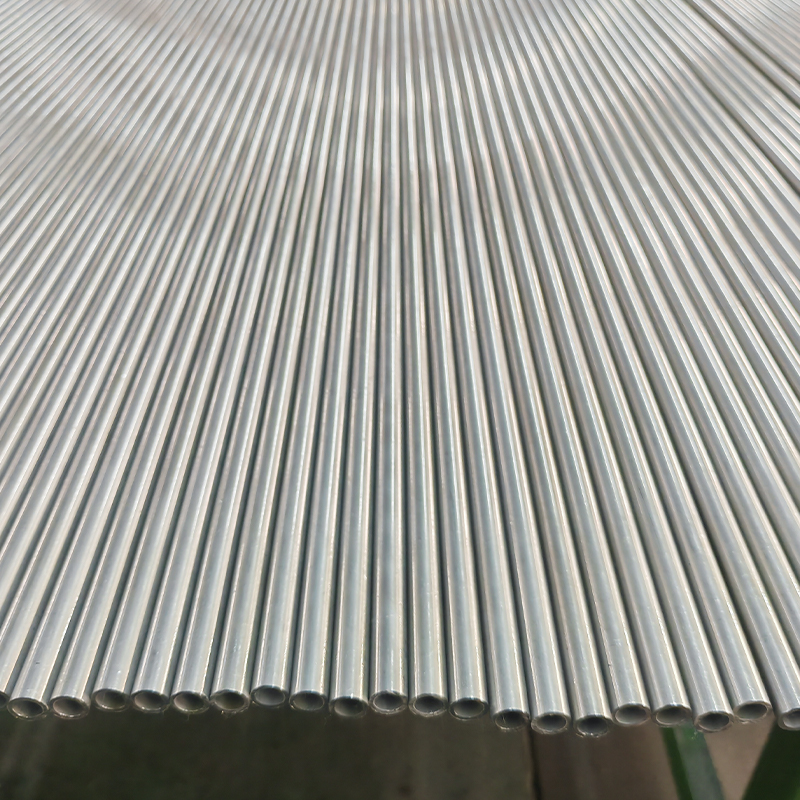
Our Hydraulic Tubes are manufactured from cold-drawn seamless steel (CDS) in com...
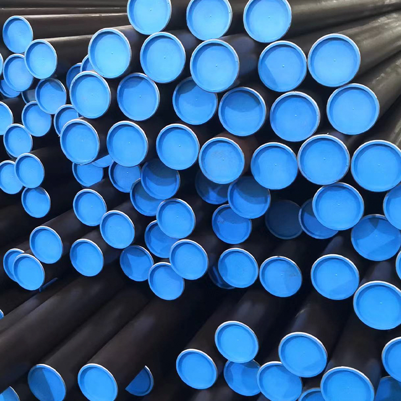
Our ASTM A519 Hydraulic Cylinder Tubes are precision-manufactured using cold dra...


